Frequently Asked Questions
We have put together a list of some of the most frequently asked questions about our various product lines. If you are unable to find the answer to your question or need further assistance please contact us here, and one of our Plexon Sales Engineers will be in contact with you as soon as possible.

Can I record and track with CineLyzer in complete darkness?
- Yes, the black & white camera option for CineLyzer can also be used for infrared imaging, which means a customer can use this camera with CineLyzer, and an IR light source, to record and track with CineLyzer in complete darkness.
How do I set up my experiment database?
- You can find detailed instructions in the CineLyzer Behavioral Research System User Guide or you can follow along with the Setting up Your Experiment Database with CineLyzer® video.
How do I set up events in CineLyzer?
- You can find detailed instructions in the CineLyzer Behavioral Research System User Guide or you can follow along with the Making Events in CineLyzer video.
How do I track behavioral files using CineLyzer?
- You can find detailed instructions in the CineLyzer Behavioral Research System User Guide or you can follow along with the CineDemo: How to Track Behavioral Files Using CineLyzer video.
How is it that the cameras are ordered in CineLyzer? For example, if a user has a four-camera system, and wants to ensure that video 1 is in chamber 1, video 2 is in chamber 2, etc., how is this achieved? Does CineLyzer number the first camera plugged in as video 1?
- The cameras are sorted by their serial numbers. The cameras with the smallest serial number will be Video 1. So, if the users need to know in advance which camera will be video 1, video 2, etc., they can look at their serial numbers on the back of FireFly cameras.
Can I place a credit card order?
- Yes you can do so here.
What is your standard shipping method?
- FedEx Express Saver (3-day) for domestic. FedEx International Economy for international.
Can you ship my order using expedited shipping?
- We will ship according to the terms on your purchase order. If you need expedited shipping, please have purchasing approve this request in writing to Plexon.
How can I submit my order?
- You can email purchase orders to orders@plexon.com or fax them to +1 (214) 369-1775.
Are headstage cables available in custom lengths? What is the maximum length I can get?
- Headstages are available in custom lengths, the maximum length for a headstage cable depends on the type of headstage cable and the type of wire used. However, Plexon recommends using the shortest length possible for analog headstage cables. This is because the cables will act as antennas and increase the amount of noise picked up along the way.
Will increasing the length of my digital headstage cable increase noise in my signal?
- No it will not.
Can you repair damaged headstage cables?
- Unfortunately, repairing damaged headstage cables is not possible. The costs associated with the repair is nearly the same as the price of a new cable. In addition, repaired cables are typically noisier and more difficult to use.
Omnetics Connectors
Does Plexon sell the Omnetics connector I need?
- Omnetics tends to have many different part numbers for the same connector. You can view the connectors we have available here https://plexon.com/products/connectors.
.
I downloaded and installed nanoZ v1.4.0 but the program won’t open due to an error code stating that FTD2XX.dll cannot be found.
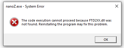
- This can be caused by a needed dynamic link library file (DLL) not being copied to a location that Windows 10 knows to look for it. The problem can be fixed by copying the appropriate DLL file to the folder “C:\Windows”.
Download the DLL file
What is the name of the connector for the NanoZ?
- The NanoZ has two Samtec connectors.
What configuration file do I need to select in the nano-Z software drop down menu for use with my Plexon nano-Z adaptor?
- Make sure that the drop down menus for the adaptor and probe say “No adaptor” and “Probe not selected.” Please note that this only applies to nano-Z adaptors built by Plexon.
How many LEDs can we have on a shank?
-
-
- Current version we are disseminating has 12 LEDs, 3 on each shank. For the next version we are
planning to make a decision among several configurations, but definitely more than 32
microLEDs per probe. We have not determined the final number yet. We should be able to
accommodate 128 individually controlled microLEDs.
- Current version we are disseminating has 12 LEDs, 3 on each shank. For the next version we are
-
What is the approximate volume of tissue illuminated by a single LED?
-
-
- The LED has a diverging Lambertian profile with an angle, and we have succeeded in optical
stimulation of neurons within tens and hundreds of microns from a single LED. However, this
probe is not meant to illuminate a large portion of the brain; it is for local stimulation, possibly
modulating at single neuron resolution.
- The LED has a diverging Lambertian profile with an angle, and we have succeeded in optical
-
Do you plan on other wavelengths than blue, for example yellow?
-
-
- Our next research goal is making color LEDs/stimulation. We are currently providing blue only. It
is unlikely to provide other wavelengths, such as yellow/red in the next year, but it is coming.
- Our next research goal is making color LEDs/stimulation. We are currently providing blue only. It
-
What is the headstage configuration/hardware requirements to test the uLED probes?
-
-
- Current headstage is using two Omnetics connectors: 32 recording sites accessed through the 36
channel Omnetics connector and 12 LEDs accessed through the 18 channel Omnetics connector.
For recording you can use any recording systems, including Intan, Plexon, TDT, etc., which are
compatible. For stimulation you can use your own stimulation instrument, even a simple function
generator. Be careful not to damage the LED. Also, the MINT hub provides the microLED
controller as an open source available at Github. Either, you can make it for yourself, or get it
from the MINT hub at manufacturing cost.
- Current headstage is using two Omnetics connectors: 32 recording sites accessed through the 36
-
Additional Information
Plexon has its own stimulating headstages, which is compatible with the uLED probes.
Also, Plexon will soon have available its own uLED Probe Control Box, which will allow
for precise control of the uLED probes. This system, which includes hardware and
software, will have digital input and output functionality, a GUI for creating patterns of
stimulation, and allow for precise control of the LEDs.
Will the LED power decrease during recording?
-
-
- We have a longevity testing of the LEDs; the power reduced a little bit but not significantly.
Probably fine for in vivo study, as there are a lot of biological variables that would impact
stimulation more than the probe technical side. The reduction of the optical power is about less
than 10%, pretty minor.
- We have a longevity testing of the LEDs; the power reduced a little bit but not significantly.
-
What is the power range of the LED light? Can they adjust independently?
-
-
- Power range can be independently adjusted by either voltage or current applied to each LED. We
recommend current control as it can safely and precisely control the optical power. You can
adjust the current from 0-100 micro-Amps, and the LED power is dependent on this.
- Power range can be independently adjusted by either voltage or current applied to each LED. We
-
Additional Information
Plexon encourages the validation of optogenetic stimulation as it exits the system prior to
entering the tissue. Plexon offers the PlexBright Light Measurement Kit which includes a power
meter and an integrating sphere photodetector.
How do you verify that the neuronal activity is due to optical stimulation and not due to the current flowing through the probe?
-
-
- We had wild animal experiments. We had an animal that was expressing channelrhosdopsin (the
target of the experiment) and the other a wild animal, no opsins expressed. We didn’t see any
current-induced or heat-induced stimulation from the wild animal. Only the animal expressing
the opsins is responding to optical stimulation. This indicates that the electrical signal is not
inducing neural activities. We also made sure that the increase in temperature of the brain is less
than one degree.
- We had wild animal experiments. We had an animal that was expressing channelrhosdopsin (the
-
Are the specifications for these probes customizable? Can I get shanks of a certain length?
-
-
- Yes and no. It requires a lot of development and engineering work to customize the probes. We
are currently getting feedback from users to find out which configurations are mostly needed
and what are the demands. If you really want to have a specific configuration, you can talk to us
and we will try to accommodate it.
- Yes and no. It requires a lot of development and engineering work to customize the probes. We
-
Additional Information
Two commonly requested probe configurations are available today from Plexon
Where can I buy these probes?
-
-
- Currently the microLED probes are being disseminated by the NSF NeuroNex Michigan hub
(MINT); but they are also translated for commercial availability. You can buy from Plexon
currently.
- Currently the microLED probes are being disseminated by the NSF NeuroNex Michigan hub
-
At what speed is it best to implant the probes to prevent bending of the shanks or dimpling of
dura/tissue?
-
-
- When you penetrate the brain, the best practice is to just go up and down until all the shanks can
penetrate. There is a recent paper that showed 2 um/second speed is the best speed to obtain
good quality recordings. As a rule of thumb, we generally reach the hippocampus in 30-60
minutes in acute recording, 1.2mm in a mouse and 2.2mm in a rat
- When you penetrate the brain, the best practice is to just go up and down until all the shanks can
-
How many times can we re-use these probes?
-
-
- The acute probe has already been used 7 times and it is still working. If you are careful with
insertion and cleaning, I think an acute probe can be reused multiple times, at least 4-5 times. In
a chronic animal it has its own complications. All of these are technically meant to be used a
single time, but it is possible to reuse them.
- The acute probe has already been used 7 times and it is still working. If you are careful with
-
Can you talk about how and where you tie the uLED ground to the recording ground in current vs voltage mode, if you ever tie them together at all?
-
-
- There are two tiny pads on the PCB where you can put a zero ohm resistor or just tie them
together.
- There are two tiny pads on the PCB where you can put a zero ohm resistor or just tie them
-
Can μLED optoelectrode heat brain tissue?
-
-
- Not really
- The amount of light we are using is very low.
- Silicon is a very good heat conductor.
- But keep in mind that long (> 10 s), continuous light stimulation can heat brain tissue.
- Not really
-
What is the best way to clean these probes?
-
- Chemical cleaning
- Overnight DI water
- Overnight contact lens solution
- Overnight DI water
- Mechanical cleaning
- Removing tissue particles with needle
- Insert probe into phantom brain
- Chemical cleaning
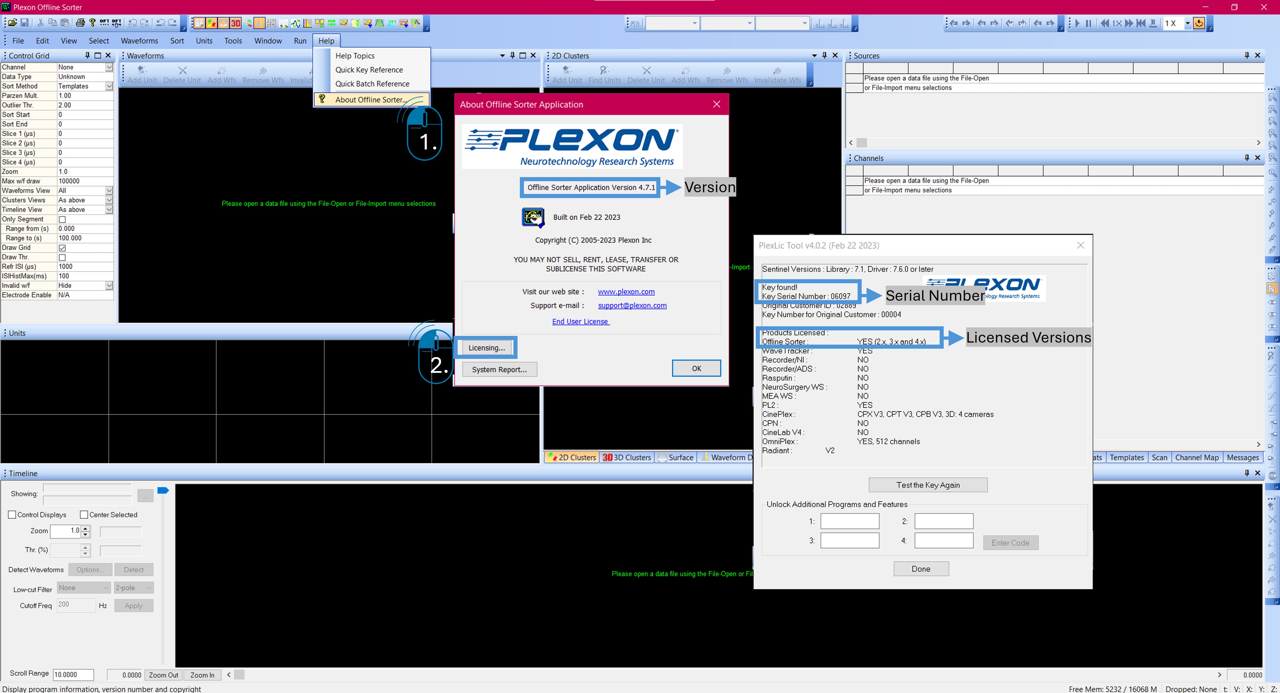
My OFS license key is not working. What should I do?
- Confirm that you are using the key that includes the license. It should look like one of these USBs

The USB key that is silver and blue includes documentation for the software and is not a valid license key.
If you are using one of the above pictured three keys and you are still having an issue with the key, you might be trying to use a version of Offline Sorter for which the key is not licensed. License keys don’t expire, but they only work for the version that was purchased.
- Check to see what version of Offline Sorter you have installed and what version your key is valid for?
The license key serial number and what versions it is licensed for are found inside the Offline Sorter program. Even if you get a message that a valid key cannot be found, you can access the license key information in the software’s demo mode. The licensing information is found under Help| About Offline Sorter.
I would like to apply both high pass and low pass filters to WB because of high frequency noise. Can I do this?
- What you are describing is a bandpass filter. A bandpass filter will allow you to apply a highpass and lowpass filter to a channel of data at the same time. The bandpass option is not available in Offline Sorter. It is only possible to apply a highpass or lowpass filter, not both at the same time. The best option for bandpass filtering is with NeuroExplorer.
I am having trouble with the template sorting option in Offline Sorter and the number of extraneous waveforms included in the unit. When I sort my data with the template method, I limit the noise to around 0.1—0.3 %. After the template is done sorting, some of the units will be upwards of 2% noise. For me, “noise” is determined by the small red percentage in the upper right-hand corner of the units window. Do you know how I can correct this?

The red percentages above the average waveform of a unit in the Units window corresponds to the percentage of waveforms within that unit violating an inter-spike interval refractory period. The refractory inter-spike interval (Refr ISI) is set in the Control Grid on the left-hand side of the Offline Sorter window. This percentage is an indication to the user that the waveforms sorted into a unit may be violating some physiological construct. In the example above, 0.4% of the waveforms sorted into the green Unit b are violating the refractory inter-spike interval set in the software. This could mean some of the waveforms in the green unit should be excluded or the inter-spike interval should be decreased. The refractory inter-spike interval red percentage is present no matter the sorting method used.
Specific to the question above, the Template sorting option in Offline Sorter is sorting all the waveforms that meet the criteria of the template set by the user. This usually means the shape of the template waveform and the fit tolerance. So long as a waveform matches the template shape within the tolerance, it will be included as part of that unit. It sounds like some percentage (I.e., 2%) of the waveforms sorted by the template method are also violating the refractory period.
It is possible to resolve this problem with one of three steps:
- Select a more representative template waveform and/or decrease the template’s fit tolerance (I.e., Make the template more selective).
- Decrease the refractory period inter-spike interval to a period more representative of the waveforms being sorted.
- Automatically remove the inter-spike interval violators. This is possible in the Tools menu. Here is a screenshot.

Does Offline Sorter work with Mac?
- Offline Sorter is only compatible with Windows 7, 8, and 10
Can Offline Sorter be run on a virtual machine (i.e. dual-booting Windows on a Mac)?
- Offline Sorter cannot be used on a virtual machine on a Mac. Offline Sorter is only compatible with Windows on a PC.
If I have a folder with 10 recordings, is it possible to use the batch file command to apply a filter to every channel on file1, export file1 as new .pl2, and then move on and repeat the process for each file in the folder?
- Yes, you can use the Dir command to accomplish this. The Dir command queues all of the files that match the template you specify for processing. Specify the folder location that you want to process, and rather than using a specific file name, use *.plx (or *.pl2). The software will then run through all files within the path that have that extension.
How do I change thresholds for my data?
- Once you have the wideband data recorded, open the .pl2 file into Offline Sorter. You’ll see a table on the right side of the screen that looks a lot like an Excel spreadsheet. Scroll down until you see a “wide band” channel- likely labeled “WB & channel number”. Double click on the channel you want to select. That will make that the “active channel” and you should see the continuous trace along the bottom of the screen. To the left of the signal trace you can select a filter type on a drop down menu, select a cut-off frequency (e.g. 250Hz), adjust your threshold (blue or red horizontal line), and then click “Detect”.
Is Offline Sorter v4 capable of loading both .plx and .nex files?
- Yes, Offline Sorter version 4 can load .plx and .nex files.
Is Offline Sorter v4 compatible with the neural data (.plx files) acquired through the MAP system?
- Yes, Offline Sorter version 4 can load .plx files from the MAP system.
In the 2D plot is there a way to show every other, or every 10th spike?
- To do this you can use the “Max w/f draw” setting (an in depth discussion can be found in the Offline Sorter User Guide, pg 43).
How do I save a file so that when opened, the sorted units appear on the continuous data? / How do I save a file such that all the data is preserved?
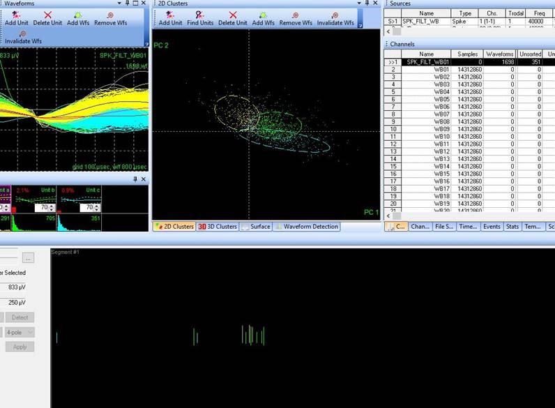
- First, open your sorted file and select the channel with the sorted spikes, which will look similar to this.
- The sorted results are there, but no continuous data. You will need to tell Offline Sorter to also show the continuous data. In the Channels window, scroll down to the channel of continuous data and right-click on the channel with the data you want to also view. Within the right-click menu is an option to “Also Show this Channel in Timeline View”
- Clicking this will add the continuous data to the Timeline.
- One tip: You may have to click single-click on the continuous channel. Sometimes the “Also Show…” option is grayed out in the right-click menu. This may be because the continuous channel is not yet selected.
What computer specifications are recommended for Offline Sorter?
- For processing large data files, we recommend a PC with lots of RAM (16GB+). An SSD will improve processing speed and for the processor, core speed matters more than the number of cores.
- 3D views in OFS require a modern OpenGL-compatible graphics card, which most modern computers have. Plexon test OFS on a PC with an Nvidia GTX1030 card, so using that or better is recommended. No actual processing happens on the graphics card, so there should be no performance benefit with something better.
How can I import a mat datafile to Offline Sorter? Check out the video tutorial: Import Data from Matlab to OFS
- There is a native import option for data from MATLAB. This is shown in the screenshot below. The option is grayed out in this screenshot because the user does not have MATLAB installed. When importing mat datafiles to OFS, the user will need to have both OFS and MATLAB installed.

I installed the 64-bit version of OFS to match the 64-bit version of MATLAB I have installed on my computer, and I added the Matlab bin directory (where libmat and libmx.dll live) to my path in Matlab, and restarted both applications, The import options still grayed out. What should I do now?
Check out the video tutorial: Import Data from Matlab to OFS
Power the computer off, then power the computer on, and then go through the below steps to see if this changes the behavior.
1) Click the “Start” (Windows) icon.
2) Click the “Settings” icon.
3) Click the “System” icon.
4) Click “About”.
5) Click “System info”.
6) Click “Advanced System Settings”.
7) At the “Advanced” tab, click “Environment Variables”.
8) At the next screen, under the “System Variables” section, click “Path”.
9) Once the “Path” line is selected, click the “Edit” button.
10) At this step, your screen should look like this.

11) Add “\win64” to the line I had selected above for editing, as marked with the red arrow in the below picture:

12) Click “OK” after making the edit. It is important to make sure to click “OK” after making the edit so that the change can be made.
13) Then, close all the windows, then power off the computer.
14) Power on the computer.
I opened a pl2 file in Offline Sorter, did some processing of the continuous data (E.g., Filtered, thresholded, referenced, etc.), spike sorted, and now I want to save. However, the Save option is greyed out. Why?

- The reason the Save and Save As options are unavailable is because a new data variable has been created in the file, which means a new pl2 file must be exported. Essentially, if you do something to the file in Offline Sorter that adds data to the file, saving is no longer an option, and exporting is required instead. This is why the Save and Save As options are greyed out.
- Some steps in Offline Sorter do not create new variables. For example, changing the sorting assignments made online in OmniPlex offline in Offline Sorter. These changes can be made without creating a new data variable, and thus the Save and Save As options are active.
Can I load .pl2 files into Offline Sorter using OFSv3?
- .pl2 support was first added to OFS v3.3.0. Please make sure you are using the most current version of the software.
How can I create a raster plot after sorting analysis?
- From Offline Sorter, users typically export the results to software that then takes those sorting assignments and turns them into visualizations. NeuroExplorer is such software. Many users also use MATLAB for these sorts of visualizations. Within Offline Sorter it is possible to export timestamp information about waveform unit assignments, which can then be used to create a raster. Generally, exporting visualizations (E.g., Raster plots) is not something done with Offline Sorter. It is not possible to create a raster itself with Offline Sorter. Offline Sorter is used to make spike sorting assignments.
We have recently encountered what appears to be waveform jitter/apparent misalignment in our recording session. I would appreciate any help figuring out why we are getting this jitter.
- Apparent Misalignment or waveform jitter is often times related to poor threshold settings. For example, a threshold too close to the noise could result in many prematurely triggered waveforms. Adjusting how waveforms are viewed in Offline Sorter, can help identify the cause of the issue. Watch this video to learn how to adjust the visualization and address apparent misalignment.
How do I create a topology with OmniPlex?
- You can find detailed instructions in the OmniPlex User Guide Release 20 or you can follow along with the How to Create a Topology with OmniPlex video.
Can my OmniPlex computer be connected to the internet? Should it be?
- Generally we don’t tell people that they should or shouldn’t connect the computer to the internet, but there have been uncommon occasions where a Windows update has caused an issue. If you can do without connecting to the internet, that would be “easiest”. If you have to be connected to the internet, you can also configure the Windows updates to not run in the background, and then run Windows updates manually when not actively in the middle of data acquisition. Windows updates running in the background while using OPX has caused some problems in the past.
Can I record EEG/EMG/EOG/EKG/ECG etc. with a Plexon system?
- Yes. In addition to the neural data channels that are processed through the headstage and front-end at 40kHz, the OmniPlex can be equipped with an auxiliary analog (AuxAI) subsystem. The AuxAI is capable of sampling up to 32 channels at 20kHz, and if needed, 4 channels at 250 kHz.
Does OmniPlex work with Windows 10?
- Yes, OmniPlex is currently compatible with Windows 7 and Windows 10.
Can I use my OmniPlex system to send out 5V TTL output to other equipment?
- Yes, you can use the Plex DO SDK to send out TTL pulses from the digital out ports that are located under the BNC connectors on the AUX I/O subsystem in the front of the OmniPlex Chassis. You can find the Plex DO SDK here on our website under the “OmniPlex and MAP Online/Client“. You can use the bare wire digital input cable to connect the digital outputs to other equipment.
How can I measure electrode impedance?
- Impedance measurement can be accomplished many different ways. Plexon recommends using the NanoZ, a device made specifically for impedance and electrode plating. The NanoZ cannot work with OmniPlex, i.e. it is not possible to measure impedance while the electrode is plugged into the headstage. You can find out more here.
When I hook up a mouse with an array or a tetrode to our Analog OmniPlex system, we get good spike activity and corresponding noise coming through. However, on the Digital OmniPlex system, there is just sparse activity. How can we change the gain on these systems so that we can see the activity?
- The two systems described are fundamentally different, and comparisons between the two need careful consideration. The “analog” system utilizes analog headstages and amplifiers, and the signal is acquired in the OmniPlex chassis, which is typically connected to the animal via at the least fifteen feet of cable, which the analog signal must travel. The need for gain in this system is to ensure the tiny signals from the brain can make it all the way to the A/D in the chassis. The signal needs to be periodically boosted along the way, such that ambient noise, cable artifact, etc. does not overwhelm the signal. Effectively, since the source of the signal (the brain) and the digitization point (the chassis) are separated by a considerable distance, gain is required.In the “digital” system this is not the case. This system utilizes a digital headstage, which is the point of acquisition. The signal is acquired extremely close to its source, so there is less of a need for multiple gain steps That said, in the digital system, the magnification settings becomes much more useful. The OmniPlex system accurately represents the signal from the brain online. And typically this signal is tiny, especially so when acquired with a digital headstage. This means the user must increase the magnification to see the signal. This is especially so when comparing with the analog system.Remember, the headstages are digital, which means there is no need for lots of gain. The signal will be really small and likely tough to see without magnification.
During the recording session, I usually select CMR to reference SPKCs. I have 1 electrode channel that is not working, Should I select CMR for all the channels, even the broken one?
- It is not recommended to include a broken electrode channel in the CMR or CAR calculation. Remember, CMR is taking the median of all the channels selected and using it as the reference. If you are including channels not of interest in the CMR calculation, the resulting reference (I.e., the median) is not a good representation of the signal and likely not a good reference. We recommend excluding the broken channel from the calculation.
How do I set up my Single wavelength photometry system?
- You can find detailed instructions in the Photometry Quick Start Guide or you can follow along with the Photometry Setup Tutorial video.
Can I measure neural activity in real time using fiber photometry?
- Yes, fiber photometry provides the most sensitive and easiest way to record neuronal activities of the deep brain structures in behaving animals. GCaMP can be used to tag cell-type specific neurons with engineered fluorescent proteins and then measure the levels of fluorescence in response to changes in intracellular calcium concentration. The fluorescence emission of the GCaMP indicator increases with elevating calcium concentration. Fiber photometry enables the researcher to record the neural activity of genetically defined subpopulations of neurons through an optic fiber in freely moving animals.
I am interested in recording from multiple animals simultaneously. Is this possible?
- Yes, the branching patch cable terminates in 4 magnetic LC ferrules. Each of these ferrules can be attached to fiber stubs on different animals.
Can I use dLight to detect changes in dopamine and a red-shifted Ca2+ indicator at the same time?
- Yes, the 465 nm LED can be used for targeting dLight and the 560 nm LED can be used for activation of the red-shifted Ca2+ indicator. The emitted fluorescence will be collected independently by each detection camera.
Will I be able to view the photometry signal during recording?
- Yes, the software included with the Plexon multi-wavelength system will show raw data for each fiber and for each detection camera. The software will also show a heat map for each fiber that illustrates changes in florescence for each fiber.
How is Plexon’s photometry system different from traditional systems?
- Traditional systems employ a single multimode optical fiber implanted in the brain, a beam splitter that separates the excitation light and the fluorescent signals of neuronal activity indicators returning through the same optical fiber, and a photodetector. This approach allows for imaging of one fiber at a time. Measuring multiple brain regions is crucial to investigate connection between different brain regions to produce behaviors and the neural correlates of social interaction. Plexon’s camera-based approach provides a cost effective means to image from multiple fibers with the same detector.
What types of behavioral tasks can be used with CineLyzer and photometry?
- T-maze
- Fear conditioning
- Operant chamber
- Elevated plus maze
- Place preference
- Barnes maze
- Novel object recognition
- Social Interaction
- Radial arm maze
- Other behavioral paradigms
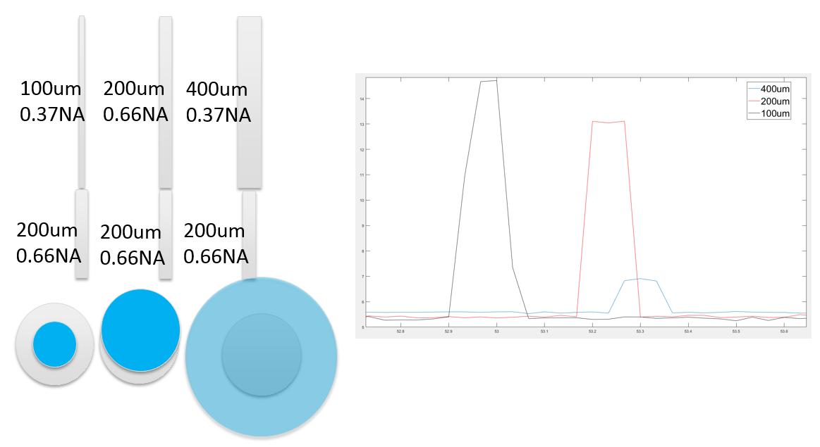
How do I know what type of fiber stubs I should use with my photometry system?
- There are many options when choosing a fiber stub. Plexon recommends using fiber stubs with a diameter of either 200/225um or 225/245um, which are both larger diameters than the diameter of the fiber used in the branching patch cable. This combination allows for the highest average output in most cases. The diagram below illustrates the power output when various combinations of patch cables and fiber stubs are used. The depiction of the 100um patch cable with the 200um fiber stub is the solution that Plexon recommends for the highest average output.
What if magnetic fiber stubs will not work with my experimental design?
- The magnetic branching photometry patch cable is made to easily attach to magnetic LC ferrules. However, this patch cable can also be connected to standard fiber stubs using a ceramic or metal sleeve.
How do I set up my PlexBright Optogenetic Stimulation system?
- You can find detailed instructions in the PlexBright User Guide or you can follow along with the PlexBright System Setup Tutorial video.
How do I measure power outputs with my system?
- Follow along with the Measuring Power Outputs with Your PlexBright Optogenetic Research System video.
Is it possible to interface with the light source through a third-party controller, or do I need the optogenetic controller with Radiant?
- The LEDs are driven by current so as long as you can control the current in a way that suits your needs then yes, the LEDs can be driven by other third party systems.
Can the LD-1 driver be used to control a laser?
- Most lasers rely upon a TTL (0-5V) pulse for control. The LD-1 driver outputs current, not voltage, so it cannot be used to generate a TTL pulse, which means it likely cannot be used to control a laser.
Is there a way to make sine functions for optogenetic stimulation protocols using the 4 channel controller and Radiant controller?
- Please see the following sections of the Radiant User Guide available here:
- Section 12 Creating Stimulation Sequence Files (.txt and .opt) pp 65
- Section 13 Assigning Stimulation Sequence Files to Channels pp 69
- Section 20 Sample Arbitrary Waveform Pattern Files pp 119
- Also, an example sine wave pattern file is installed with the Radiant software package. This example is installed by default here: C:\PlexonData\Sample Pattern Files\.
I lost my BNC cables that came with my optogenetic controller, can I use any BNC cable with my 1 channel driver or 4 channel controller?
- No, Plexon provides insulated BNC cables that prevent the outer contacts from touching. This is particularly important when using the controller in current output mode. The circuit that sets the current output relies on measuring the return current, so if the outer BNC contact were shorted to ground through accidental contact with something else (a metal table for example), the output current would go to unexpectedly high values.
What LED would I use if I wanted to activate a certain rhodopsin?

How do I get started with HELIOS?
- You can follow along with the HELIOS Quick Tutorial to learn how to start using your HELIOS device.
What is the battery life of the LED?
- The life of the LED battery depends on the power of the LED and the time it is on during the experiment. It can be recharged approximately 400 times, or last 2-3 years.
How many HELIOS devices can be used at the same time? How long is the working distance?
- The number of HELIOS systems that can be used at a time depends on whether the experimenter wants the animals to receive separate stimulation patterns. Several HELIOS systems receiving the same stimulation pattern can be used at once, but the transmitters must be separated (with a barrier to IR stimulation) to control separate stimulation patterns. You cannot send two different stimulation patterns to the same area.
- The working distance is approximately 2 feet, however, multiple transmitters can be used for larger arenas.
Will an infrared camera interfere with the HELIOS device?
- If the infrared light has a frequency of infrared output that is similar to the HELIOS transmitter, then this will interfere with the HELIOS system.
How heavy is the HELIOS device?
- The weight is 2.8g, which includes the battery.
How do I control the HELIOS device?
- Control is via TTL, which means any device you have capable of sending out a pattern of TTL pulses should work. Alternatively, Plexon offers its own software-control device, which enables the user to create complex patterns of TTL outputs.
What wavelengths is HELIOS available in?
- Blue – (465nm/300mA)
- Green – (525nm/300mA)
- Lime – (550nm/500mA)
- Orange – (620nm/250mA)
Should I use stainless steel jacketing for my experiment with mice?
- Most of the time, mono-coil and stainless steel jacketed cables are too heavy for mice. The stainless steel jacketed cables are even heavier than the mono-coil cables.
Do patch cables come in custom lengths?
- Yes, High Durability or High Performance cables can be made in custom lengths to the nearest tenth of a meter. The maximum length for High Performance patch cables is 2.3 meters, while High durability patch cables can be made in any length to the nearest tenth of a meter.
What is the difference between High Durability and High Performance fibers?
- High Durability fibers have a lower numerical aperture than the High Performance fibers at .5NA, but may be more optimal in experiments in highly active animals. The High Performance fibers on the other hand have a numerical aperture of .66 with all glass construction, which makes it heat, chemical, and scratch resistant. The High Performance patch cable provides the highest possible output intensities from PlexBright LED Modules.
What is the benefit of magnetic fiber stubs? Are these available in both LC and FC?
- Magnetic fiber stubs allow for rotational movement such as spinning and twirling at the connection in freely behaving animal experiments, reducing torque on the implant. These are only available with LC Ferrule tips. Also, the magnetic attachment allows for easier attachment of the patch cable to the fiber stub. View a video of this connection here.
How do ThorLabs and Plexon patch cables differ?
- The main difference is in power output. The outputs reported on the ThorLabs website are substantially lower than those reported on ours. Part of this is due to the type of fiber used for the patch cables. Plexon uses a proprietary high-NA fiber to maximize the power output from our LEDs. If you look at our power outputs at the tip of a patch cable, you will get 3x the power with a blue LED module.
Advice from the Field — Plexon Probes Edition
- Some advice straight from current Plexon customers. If you would like to know more or have any further questions please contact one of our Plexon Sales Engineers.
What is the difference between U, V, and S probes?
- All three configurations are multi-use, multi-site linear electrodes, the difference being in their tips. The U-Probe is robust with a blunt tip angle and is most often used for acute studies with larger animals such as primates, while the S-Probe has a solid stainless steel tip and is the strongest of the three tip designs, similar to a sharpened pencil, and while not recommended for puncturing dura, customers who must do so may have better success with the S-Probe tip. The V-Probe has a tapered, conical-shaped tip for easier penetration and reduction of trauma upon entry, in addition this specialized tip permits the recording site to be closer to the tip of the probe.
How to I determine the specifications of a probe from the probe name on the case?
- Use the guide found here to identify the specifications of your probe.
What is the lead time for custom probes?
- 4-6 weeks
What is the reinforcement tube for?
- The reinforcement tube has two functions: 1) It reinforces or strengthens the junction between the thinner recording tube (where the electrode sites are) and the connector block, which is the interface to the recording headstage, and 2) it allows for a convenient connection point for the microdrive. Most probe users attach the microdrive to the reinforcement tube. The reinforcement tube is thicker in diameter than the recording tube, which allows for a strong connection point.
Where can the fluid capillaries be located?
- Fluid channels can be placed between any two sites in a S or U probe. Fluid channels on a V probe must be placed in the first half of the sites closest to the connector.
How should I sterilize my probe before use?
- We recommend ethylene oxide gas or UV sterilization. Alcohol is not a sterilant, but can be carefully used if EtOH or UV light is not available. However, the longer the probe – and specifically the tip – is exposed to alcohol the more likely the epoxy holding the wires in place will soften. While probes may be rinsed briefly with alcohol, they must be allowed to air dry immediately thereafter. The tips of the probe must not be allowed to sit in alcohol for more than 15 seconds as exposure to alcohol runs the risk of dissolving or damaging the epoxy which holds the electrode sites in place.
What is the inner and outer diameter of fluid channels on probes?
- The inner diameter is 40μm and the outer diameter is 60μm.
What is the expected impedance of the U- V-, and S-probes?
- Electrodes within Plexon u-, v-, and s-probes are not designed to be a specific impedance. The probes are specifically built for single-unit isolation, although we do not expect a specific impedance. The individual electrodes are typically 15um diameter wire.
Does Plexon have a recommendation for microdrives?
- Plexon has put together a list of microdrives as a reference. You can view this information here: https://plexon.com/recommended-microdrives/
Do you have any suggestions for reducing noise in a linear probe with a fluid channel?
- The fluid line connector/tubing should be shielded/grounded. The best way to avoid this is to wrap the drug tubing in aluminum foil and ground it.