High Channel Count Headstages
The 64 and the 128 channel digital headstages from Plexon are now available. These headstages utilize novel Samtec connectors, which allow for small, compact, and light-weight packages. The novel connector design means smaller and cheaper electrode interfaces.
The Samtec connector compatible with the 64 channel headstage is available now on the N-form arrays and U-, V-, and S-probes. Plexon also offers an electrode interface board (EIB) for the Samtec connector, which can be used to interface individual wires or tetrodes to the headstage.


64 Channel Headstage
Description:
A 64-channel thumbtack design digital headstage with a Samtec connector interface. HST/64DS is also alternatively available
with on board red, green, or blue LEDs (in any combination) or with LED sockets for the ability to add LEDs in the future. Custom
electrode interface boards are available for HST/64DS.
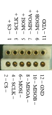
Input Connector Information: Single piece Samtec connector #12
Note: The single piece Samtec connector requires no special alignment. The mating force with this connector is considerably
less than the combined Omnectics connectors, without sacrificing a solid and reliable feel.

Input Mating Connector 12: Female
Plexon Catalog Number: CON/64f-Samtec
Samtec Part Number: SEAF8-10-05.0-S-08-2-K

Input Connector 12: Male
Catalog Number: CON/64m-Samtec
Samtec Part Number: SEAM8-10-S02.0-S-08-2-K
Thumbtack Design:

Headstage Cable Information:
The HST/64DS headstage connects to the DHP unit through the HSC/DHSC2 or HSC/DHSC4 cable.
128 Channel Headstage (Gen 1 and Gen 2)
Description:
A 128-channel thumbtack design digital headstage with a Samtec connector interface. HST/128DS is also alternatively available
with on board red, green, or blue LEDs (in any combination) or with LED sockets for the ability to add LEDs in the future. Custom
electrode interface boards are available for HST/128DS.
HST/128 Gen 1 is a legacy part. HST/128 Gen 2 headstages use a new Samtec input connectors. The main difference between the
Gen 1 and Gen 2 input connectors is in the size and location of the guide post feature of the connectors.
Note that, in general, HST/128 Gen 2 headstages do not mate with accessories made with Gen 1 connectors and similarly Gen 1 headstages
do not mate with accessories made with Gen 2 connectors.
Input Connector Information: Samtec connector #13a
Note: The input connector is a pair of Samtec ADM6-20-01.5-L-04-2 Gen 1 connectors. The connectors are spaced 6.35 mm apart.

Input Mating Connector 13a: Female
Plexon Catalog Number: CON/128f-Samtec Gen 1
Samtec Part Number: ADF6-20-03.5-L-04-2 Gen 1

Input Connector 13a: Male
Catalog Number: CON/128m-Samtec Gen 1
Samtec Part Number: ADM6-20-01.5-L-04-2 Gen 1
Input Connector Information: Samtec connector #13b
Note: The input connector is a pair of Samtec ADM6-20-01.5-L-04-2 Gen 2 connectors. The connectors are spaced 6.35 mm apart.

Input Mating Connector 13b: Female
Plexon Catalog Number: CON/128f-Samtec Gen 2
Samtec Part Number: ADF6-20-03.5-L-04-2 Gen 2

Input Connector 13b: Male
Catalog Number: CON/128m-Samtec Gen 2
Samtec Part Number: ADM6-20-01.5-L-04-2 Gen 2
Thumbtack Design:

Headstage Cable Information:
The HST/128DS headstage connects to the DHP unit through the HSC/DHSC2 or HSC/DHSC4 cable.
Digital Samtec Headstages
| Channels Pins | Headstage Catalog Number* | Gain Dimensions** Weight*** | LED Compatibility Latch Compatibility Additional Information |
| U 64 channels 72 pins 4 reference pins 4 ground pins | HST/64DS | N/A gain inches: 0.47L x 0.55W x 0.61D mm: 12L x 14W x 15.5D grams: 1.45 | LED: Up to 2 Latch: No Additional Information:
|
| V 128 channels 160 pins 16 reference pins 16 ground pins | HST/128DS Gen 1 | N/A gain inches: 0.83L x 0.47W x 0.39D mm: 21L x 12W x 10D grams: 1.75 | LED: Up to 2 Latch: No Additional Information:
|
| V2 128 channels 160 pins 16 reference pins 16 ground pins | HST/128DS Gen 2 | N/A gain inches: 0.83L x 0.47W x 0.39D mm: 21L x 12W x 10D grams: 1.75 | LED: Up to 2 Latch: No Additional Information:
|
*Image size: please note that product images below are not to scale relative to either actual size or to each other.
**Product dimensions: headstage lengths include the longest pin; the addition of either a latch and/or LEDs can increase the dimensions listed below slightly.
***Product weights: headstage weights may vary ever so slightly due to the hand-crafted nature of the products; the addition of either a latch and/or LEDs can also impact the weights listed below slightly.
Guides and How To Papers
For 8, 16, 32, 64 and 128 Channel Digital Headstages
Technical Specs and Data Sheets
Connector Pin-out, Ground and Reference Information
64 Channel Headstage
Dedicated reference; programmably groundable
The figure below shows which pins on the connector are recording inputs, which pins are connected to the (single) reference input, which pins are connected to ground, and which pins are not connected. The figure on the right below shows the Plexon channel numbers assigned to each of the recording inputs.


Input Reference: Pins R1, R2, R3, and R4
- This input can be used to connect a dedicated reference electrode. It can be grounded programmatically from OmniPlex Server if no reference electrode is present or if you want to disregard the signal from the reference (for example, if the reference electrode is broken).
- Set the reference option in OmniPlex Server to “True reference” to subtract the signal from the reference electrode. It is typically connected to a de-insulated electrode and used as a local reference for spike channels.
- Set the reference option in OmniPlex Server to “Grounded reference” to ground the input when no reference electrode is present or when you want to disregard the signal from the reference electrode. This is typically used as a distant reference for field potentials, and also for spike channels.
Input Ground: Pins G1, G2, G3, and G4
- The ground on G1, G2, G3 and G4 are identical. Use any or all of these pins to ground the animal via skull screw or cannula, and make sure it touches the cerebrospinal fluid.
Note
- When using a version of OmniPlex prior to 17.0, please contact Plexon Support for a channel mapping file
128 Channel Headstage
Dedicated reference; programmably groundable
The figure below shows which pins on the connector are recording inputs, which pins are connected to the (single) reference input, which pins are connected to ground, and which pins are not connected. The figure on the right below shows the Plexon channel numbers assigned to each of the recording inputs.
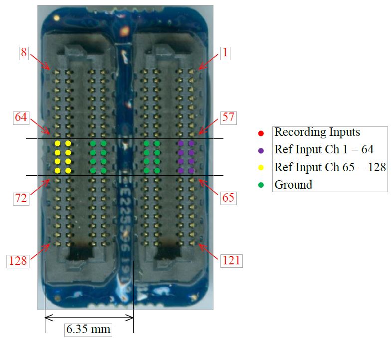
Input Reference Channels 1-64:
- These inputs can be used to connect a dedicated reference electrode. They can be used as a point of reference for channels 1-64.
- Set the reference option in OmniPlex Server to “True Reference” to subtract from the reference electrode(s). It is typically connected to a de-insulated electrode and used as a local reference for spike channels.
- Set the reference option in OmniPlex Server to “Grounded Reference” to ground the input when no reference electrode(s) is present or when you want to disregard the signal from the reference electrode(s). This is typically used as a distant reference for field potentials, and also for spike channels.
Input Reference Channels 65-128:
- These inputs can be used to connect a dedicated reference electrode. They can be used as a point of reference for channels 65-128.
- Set the reference option in OmniPlex Server to “True Reference” to subtract from the reference electrode(s). It is typically connected to a de-insulated electrode and used as a local reference for spike channels.
- Set the reference option in OmniPlex Server to “Grounded Reference” to ground the input when no reference electrode(s) is present or when you want to disregard the signal from the reference electrode(s). This is typically used as a distant reference for field potentials, and also for spike channels.
Input Ground: Pins G1-16
- The ground on pins G1-G16 are identical. Use any or all of these pins to ground the animal via skull screw or cannula, and make sure it touches the cerebrospinal fluid.
Note
- When using a version of OmniPlex prior to 17.0, please contact Plexon Support for a channel mapping file