Plexon V-Probe
The V-Probe takes the best of the very popular U-Probe to the next level, while also leveraging the benefits of the redesigned, conical-shaped tip to further minimize trauma to the brain tissue upon insertion. It is exceptionally durable, highly customizable, and often used in acute research with medium to large animals.
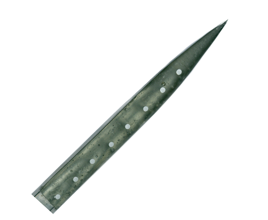
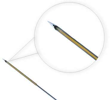
The V-Probe is a multi-use, multi-site, linear electrode with recording sites positioned on the side of a sharpened, symmetric cone. Compared with our very popular U-Probe, the cone-shaped tip is believed to result in less trauma to the brain tissue upon penetration by minimally displacing tissue along the track. The new design also permits an electrode site to be placed closer to the tip of the neural probe.
V-Probes are made in a single-row configuration, with a choice of 8, 16, 24, 32, or 64 channels, in lengths up to 150 mm.
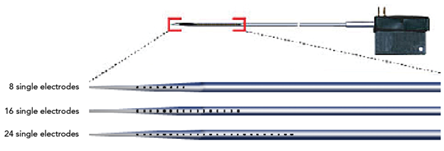
The platinum/iridium electrode recording sites are available in 15, 20, 25 and 40 µm diameter options. The small electrode site diameter (15 µm) enables effective single-unit recording, while a unique etching process of the electrode surface results in lowered impedances without significantly changing the overall surface area of the exposed recording site. The result is a small site suitable for resolving single units coupled with low impedance for a better signal-to-noise ratio.
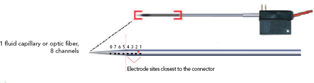
V-Probes also come with the flexibility of integrating up to four fluid channels or optical fibers at specified locations – sites 1-4 illustrated in the 8 channel configuration below. Please see the Technical Spec tab for more information on correct placement.
Like U-Probes, V-Probes are exceptionally robust due in part to their hand-crafted, stainless steel construction (as opposed to silicon), and ability to penetrate deep within the brain. When used according to proper procedures, V-Probes will support many uses over a long period of time. Reusing the exact V-Probe from experiment to experiment is not only economical, but more importantly removes one element of potential variability.
You may also wish to explore other options in Plexon’s family of Specialty Probes, Electrodes and Arrays including our Thumbtack Probe for chronic application with medium to large animals.
Neural probes can be purchased independently or operated in conjunction with the OmniPlex® Neural Data Acquisition System. Your Plexon Sales Engineer is happy to provide additional information and to assist you in determining what might be the most advantageous neural probe configuration.
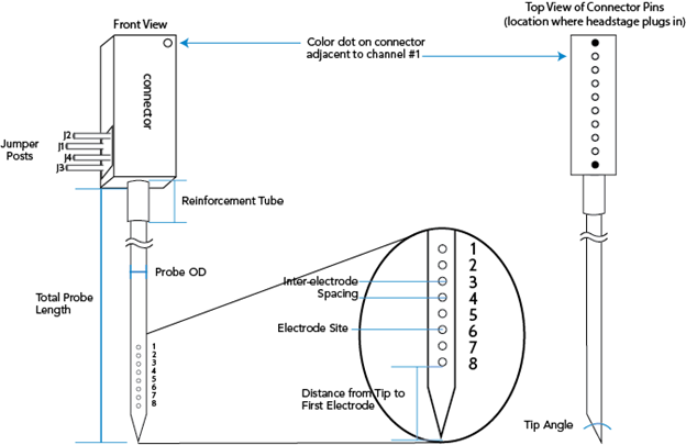
The illustration below depicts the anatomy of a standard V-Probe by front and top (connector) view. The 8 channel, single electrode configuration is featured as the example (see page 7 of the V-Probe Technical Guide located in the Resources tab for more details on this particular channel count). Electrode sites are numbered accordingly (sites 1 – 8 from connector to tip).
 |
V-Probes are rather customizable, as outlined in the table below. It is possible that V-Probes may be made outside of the specifications indicated. As such, it is recommended that you discuss your needs with a Plexon Sales Engineer to determine if your unique request may be accommodated.
| Feature | Specifications and Options | Remarks |
| Application | In vivo; acute | |
| Channel counts | 8, 16 24, 32, or 64 | |
| Total probe length | 30 to 150 mm | Length is customizable within range provided; however, the most typical request is 100 mm. Total probe length is measured from tip to the connector. The difference between the total neural probe length and the reinforcement tube length is a minimum of 25 mm. |
| Probe OD | 185 to 360 μm | Neural probe diameters vary based on the number of electrodes, fluid channels and optic fibers. See the Probe diameter tables found in the Probe Technical Guide under Technical Specifications. |
| Reinforcement tube length | 5 to 125 mm | Length is customizable within range provided |
| Reinforcement tube outer diameters | 460 or 640 μm | Neural probe diameters of 236 μm and greater require a 640 μm reinforcement tube |
| Electrode construction | 15 μm Pt/Ir electrode site diameter, circular shape, HML insulated (polyimide), and secured in medical-grade epoxy | |
| Electrode configurations | Single | |
| Inter-electrode spacing | 50 μm, 75 μm, 100 μm, 150 μm, or 200 μm along length of probe | 64 Channel probes with a single electrode configuration are available with 50, 75, or 100um inter-electrode spacing. |
| Distance from tip to the closest electrode site | 300 μm | The numbering of the electrode sites is such that channel #1 is closest to the connector. Conversely, the electrode site closest to the tip is the largest channel # on the neural probe. |
| Stimulation options | Single: Up to four fluid capillaries and/or optic fibers | Single: Able to accommodate up to four fluid capillaries/optic fibers. Must be placed within the half of sites closest to the connector. Examples: four fluid capillaries; or four optic fibers; or one fluid capillary with three optic fibers. The total count of fluid capillaries plus optic fibers may not exceed four. 64 channel neural probes are able to accommodate 1 fluid capillary/optic fiber. |
| Fluid capillary ID | 40 μm | Fluid capillaries are slightly offset from the center line of the electrodes. |
| Fluid capillary OD | 60 μm | |
| Optic fiber OD | 50 μm | Optic fibers are slightly offset from the center line of the electrodes. |
| Connector interfaces | 8 channel: CON/8o50m-10P 16 channel: 2x CON/8o50m-10P, CON/16m-V 24 channel: 3x CON/8o50 or CON/32m-V 32 channel: CON/32m-V 64 channel: 2x CON/32m-V or CON/64f-Samtec | Omnetics and Samtec connectors. |
| Lifespan | Robust and reusable with a minimum of thirty penetrations, likely many more |
The V-Probe diameter table below provides the minimum diameters for all electrode, fluid capillary and optic fiber combinations.
Single Electrode Configuration:
| Channels | Fluid Capillaries or Optic Fibers | Minimum Probe Diameter (μm) ^ | Minimum distance from tip to 1st electrode (μm) | Reinforcement tube diameter (μm)^ |
| 8 | 0, 1 | 185 | 300 | 460 or 640 |
| 8 | 2 | 210 | 300 | 460 or 640 |
| 8 | 3 | 260 | 300 | 640 |
| 8 | 4 | 300 | 300 | 640 |
| 16 | 0 | 185 | 300 | 460 or 640 |
| 16 | 1 | 210 | 300 | 460 or 640 |
| 16 | 2 | 236 | 300 | 640 |
| 16 | 3 | 300 | 300 | 640 |
| 16 | 4 | 320 | 300 | 640 |
| 24 | 0 | 210 | 300 | 460 or 640 |
| 24 | 1 | 236 | 300 | 640 |
| 24 | 2 | 300 | 300 | 640 |
| 24 | 3 | 320 | 300 | 640 |
| 24 | 4 | 360 | 300 | 640 |
| 32 | 0 | 260 | 300 | 640 |
| 32 | 1 | 260 | 300 | 640 |
| 32 | 2 | 300 | 300 | 640 |
| 32 | 3 | 320 | 300 | 640 |
| 32 | 4 | 360 | 300 | 640 |
| 64 | 0 | 320 | 300 | 640 |
| 64 | 1 | 360 | 300 | 640 |
*V-Probes are manufactured by Neuronelektród.
^Batch variation in tubing inner diameter may require a larger neural probe diameter or larger reinforcement tube.
Our linear probes are extremely customizable, some of our most popular custom options include:
Variotrodes Probe:
These multi-use, multi-site linear electrodes are custom-made probes that allow the inter-electrode space to be varied between 50μm – 500um along the length of probe.
Oval-Sites Probe:

The linear U-, V- and S-probes can be manufactured not only with round electrode sites, but with oval-sites as well. Oval sites result in the contact surface of the electrode pad being twice as large as that of a round site, without increasing the diameter of the probe shaft.
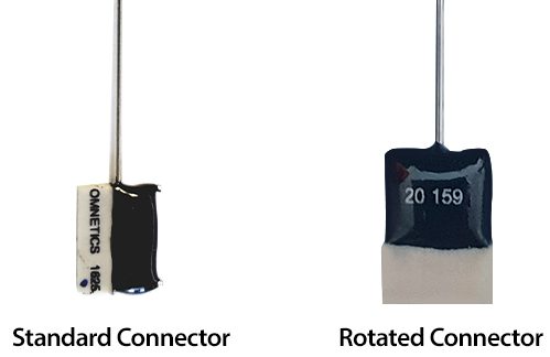
Rotated connector:
Rotating the connector 90 degrees allows for the headstage to be plugged in from the top which can alleviate spacing issues.
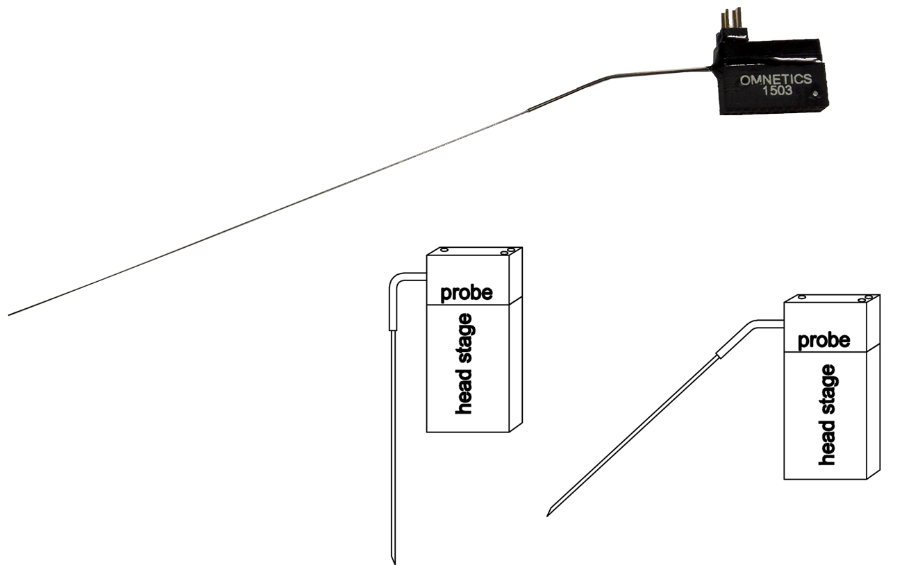
Kinked/Angled Reinforcement Tube:
Probes can be made with a “kink” in the reinforcement tube. Customers specify the angle and the location of this bend. Changing the angle of the reinforcement tube can make it easier to plug in the headstage when recording from brain regions close together.
Fluid Channels:
Up to 4 fluid delivery channels for precise drug delivery can be added to S, U, and V-Probes. The placement of these fluid channels depends on the type of probe chosen. A connector steel tube (360um OD) is pulled over the fluid capillary (60um OD) and polyethylene or silicone tubing can be used to connect to the injection system.

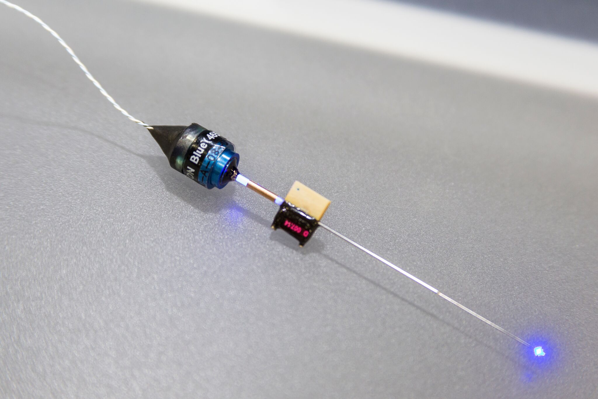
Fiber Optics:
Up to 4 fiber optic lines for optogenetic stimulation can be added to S, U, and V-Probes and intermixed within the recording sites. The placement of these fiber optics depends on the type of probe chosen. Probes will be manufactured with a LC ferrule that can be used to connect to your light source.
Jumper Location:
You can have the location where the jumper cables connect moved to better fit your experimental designs. For example, jumpers can me moved so that they are accesible from the side.
“Pig-Tail” Connector Design:
The unique pig-tail connector design allows for greater flexibility with site orientation and easier movement of the probe while in the microdrive. The length of the cable between the reinforcement tube and the connector can be customized.
Guides and How To Papers
Technical Specs and Data Sheets
Other Resources
Design Your Own Probe
Use the interactive form below to see what your probe might look like with different configurations. If you find a configuration you like and would like to have a Sales Engineer contact you about it, please enter your name, email, and principal investigator and we’ll get back to you.