Optogenetics and Neural Recording
There are many advantages of combining optogenetics with conventional electrophysiological approaches in experimental studies. Adding optic fibers to linear probes allows researchers to to classify and characterize neurons so that the roles of individual neurons can be identified within local circuits.
Optic Fibers can be placed along any of our Linear Probe offerings (U-, V-, and S-Probes). Up to 4 fiber optic fibers for optogenetic stimulation can be added linear probes and intermixed within the recording sites, allowing for neural recording and optogentic stimulation.
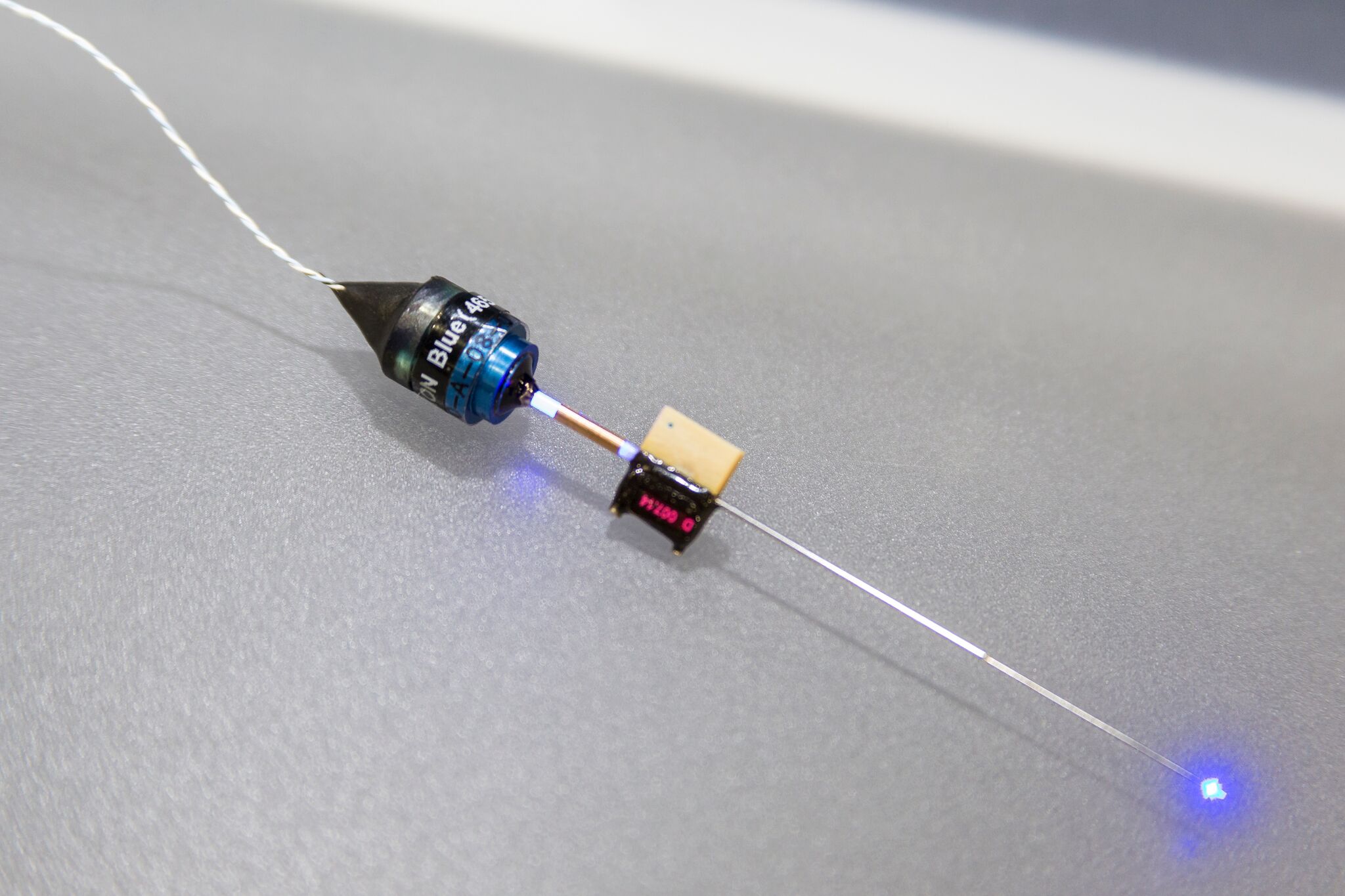
Fiber Optic Connector:

Probes will be manufactured with an LC ferrule that can be used to connect to your light source. Ceramic or metal sleeves can be used to attach the patch cable directly to the ferrule on the probe.
Dual Fiber Optic Schematic:

When a probe contains multiple fibers, the LC ferrules will be labeled to identify which location corresponds to which ferrule. The ferrule marked with “1” corresponds to the fiber closest to the connector. The placement of these fiber optics depends on the type of probe chosen.
- Fibers can be placed between any two sites on U and S Probes
- Fibers can be placed between the first half of sites closest to the connector on V-Probes.
- Fibers will be placed slightly off centered of the electrode sites.
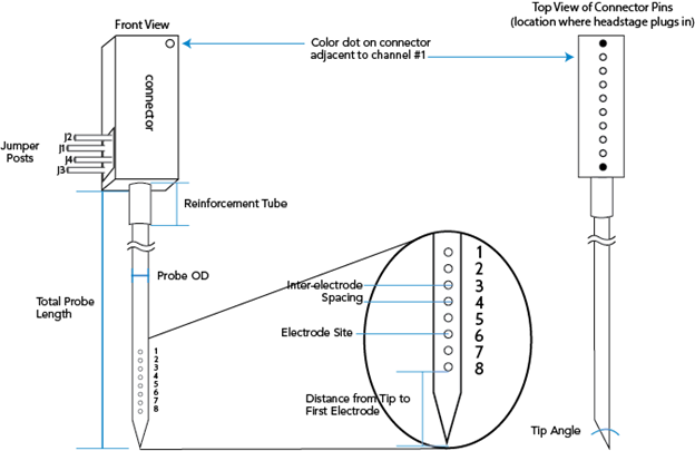
The illustration below depicts the anatomy of a standard U-Probe by front and top (connector) view. The 8 channel, single electrode configuration is featured as the example (see page 8 of the U-Probe Technical Guide located in the Resources tab for more details on this particular channel count). Electrode sites are numbered from connector to tip.
U-Probes are customizable, as can be seen from the table below. It may also be possible to produce neural probes beyond the specifications below. As a result, it is recommended that you discuss your needs with a Plexon Sales Engineer to determine the best configuration and if your unique request can be accommodated.
| Feature | Specifications and Options | Remarks |
| Application | In vivo; acute | |
| Channel counts | 8, 16, 24, 32, or 64 | |
| Total probe length | 30 to 150mm | Length is customizable within range provided; however, the most typical request is 100mm. Total neural probe length is measured from tip to the connector. The difference between the total probe length and the reinforcement tube length is a minimum of 25mm. |
| Probe OD | 185 to 360 μm | Neural probe diameters vary based on the number of electrodes, fluid channels/optic fibers, and tip profile . More information here: U-Probe, S-Probe, or V-Probe. |
| Reinforcement tube length | 5 to 125mm | Length is customizable within range provided |
| Reinforcement tube outer diameters | 460 or 640 μm | Neural probe diameters of 236 μm and greater require a 640 μm reinforcement tube |
| Electrode construction | 15 μm Pt/Ir electrode site diameter, circular shape, HML insulated (polyimide), and secured in medical-grade epoxy | |
| Electrode configurations | Single, stereotrode or tetrode | Single configuration is most typical; stereotrodes and tetrodes tend to be used in areas with an especially high density of neurons (i.e. hippocampus). |
| Inter-electrode spacing | 50 μm, 75 μm, 100 μm, 150 μm, or 200 μm along length of probe; 50 μm within stereotrode or tetrode group | 64 Channel neural probes are available in single and stereotrode configuration. 64 Channel probes with a single electrode configuration are available with 50, 75, or 100um inter-electrode spacing. 64 channel probes with stereotrode configuration require 100um or 150um interelectrode spacing. |
| Distance from tip to the closest electrode site | Dependent on neural probe diameter and tip profile. More information here. | The numbering of the electrode sites is such that channel #1 is closest to the connector. Conversely, the electrode site closest to the tip is the largest channel # on the probe. |
| Stimulation options | Single: Up to four fluid capillaries and/or optic fibers Stereotrode or Tetrode: Up to two fluid capillaries and optic fibers | Single: Able to accommodate any combination of up to four additional fluid capillaries/optic fibers. Examples: four fluid capillaries; or four optic fibers; or one fluid capillary with three optic fibers. The total count of fluid capillaries plus optic fibers may not exceed four. Stereotrode or Tetrode: Able to accommodate any combination of up to two additional fluid capillaries/optic fibers. The same examples that apply for the single configuration above apply here, however, the total count of fluid capillaries plus optic fibers may not exceed two. 64 channel neural probes are able to accommodate 1 fluid capillary/optic fiber. |
| Fluid capillary ID | 40 μm | Fluid capillaries are slightly offset from the center line of the electrodes. |
| Fluid capillary OD | 60 μm | |
| Optic fiber OD | 50 μm | Optic fibers are slightly offset from the center line of the electrodes. |
| Connector interfaces | 8 channel: CON/8o50m-10P 16 channel: 2x CON/8o50m-10P, CON/16m-V or CON/16o25m-18P 24 channel: 3x CON/8o50 or CON/32m-V 32 channel: CON/32m-V 64 channel: 2x CON/32-mV or CON/64f-Samtec | Omnetics and Samtec Connectors. |
| Lifespan | Robust and reusable |
The two U-Probe diameter tables below provide the minimum diameters for all electrode, fluid capillary and optic fiber combinations.
Single Electrode Configuration:
| Channels | Fluid Capillaries or Optic Fibers | Minimum Probe Diameter (μm)^ | Minimum distance from tip to 1st electrode (μm) | Reinforcement tube diameter (μm)^ |
| 8 | 0, 1 | 185 | 320 | 460 or 640 |
| 8 | 2 | 210 | 360 | 460 or 640 |
| 8 | 3 | 260 | 450 | 640 |
| 8 | 4 | 300 | 520 | 640 |
| 16 | 0 | 185 | 320 | 460 or 640 |
| 16 | 1 | 210 | 360 | 460 or 640 |
| 16 | 2 | 236 | 410 | 640 |
| 16 | 3 | 300 | 520 | 640 |
| 16 | 4 | 320 | 560 | 640 |
| 24 | 0 | 210 | 360 | 460 or 640 |
| 24 | 1 | 236 | 410 | 640 |
| 24 | 2 | 300 | 520 | 640 |
| 24 | 3 | 320 | 560 | 640 |
| 24 | 4 | 360 | 620 | 640 |
| 32 | 0 | 260 | 450 | 640 |
| 32 | 1 | 260 | 450 | 640 |
| 32 | 2 | 300 | 520 | 640 |
| 32 | 3 | 320 | 560 | 640 |
| 32 | 4 | 360 | 620 | 640 |
| 64 | 0 | 320 | 560 | 640 |
| 64 | 1 | 360 | 620 | 640 |
^Batch variation in tubing inner diameter may require a larger neural probe diameter or larger reinforcement tube
Stereotrode/Tetrode Configurations:
| Channels | Fluid Capillaries or Optic Fibers | Minimum Probe Diameter (μm)^ | Minimum distance from tip to 1st electrode (μm) | Reinforcement tube diameter (μm)^ |
| 8 | 0-1 | 185 | 320 | 460 or 640 |
| 8 | 2 | 210 | 360 | 460 or 640 |
| 16 | 0 | 185 | 320 | 460 or 640 |
| 16 | 1, 2 | 236 | 410 | 640 |
| 24 | 0 | 210 | 360 | 460 or 640 |
| 24 | 1,2 | 260 | 450 | 640 |
| 32 | 0 | 260 | 450 | 640 |
| 32 | 1,2 | 300 | 520 | 640 |
| 64** | 0 | 320 | 560 | 640 |
| 64** | 1 | 360 | 620 | 640 |
*U-Probes are manufactured by Neuronelektród.
**Available in Stereotrode configuration with interelectrode spacing of 100um or 150um
^Batch variation in tubing inner diameter may require a larger neural probe diameter or larger reinforcement tube.
Guides and How To Papers
Technical Specs and Data Sheets