nanoZ Adaptors – Samtec (Con/64 and Con/128)
Plexon is pleased to offer the NanoZ™ multi-electrode impedance tester. In addition, we offer adaptors so that the NanoZ can be used with a wide range of electrodes. High channel count headstages from Plexon use Samtec connectors, which are identified as CON/64 and CON/128. The information below describes adaptors that have been designed to interface these connectors with the NanoZ.


nanoZ to SEAM8 Adaptor (for use with 64 channel headstages)
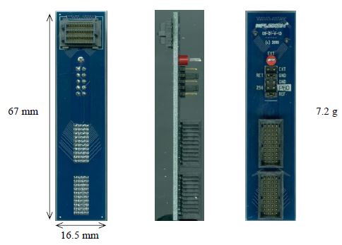
This is a nanoZ to SEAM8 (aka CON/64) adaptor. The nanoZ measures the impedance of up to 64 electrodes relative to a return electrode (RET). By default the 64 channels of the nano Z are connected to the 64 Plexon channels of the electrode as described below. After an electrode array has been implanted, the impedance of the electrodes is typically measured relative to the ground electrode (GND) within the array. Prior to implantation, the impedance of the electrodes, including the ground and reference electrodes, can be measured relative to an external electrode (EXT) that is not part of the array. This is particularly useful for verifying the integrity of the ground and reference electrodes prior to implantation.
 To measure impedance relative to the ground (GND) electrode within the array, position the jumper (above the dotted line) as shown in Figure 1 to the left. This configuration is typically used for in vivo impedance measurements of chronically implanted electrode arrays.
 To measure the impedance of the reference electrode relative to the ground electrode, position the jumper (below the dotted line) as shown in figure 2. In this configuration channel 56 of the nanoZ, which is typically connected to Plexon electrode 60, will be connected to the reference electrode instead.
 To measure the impedance of the electrodes relative to an external electrode, position the jumper (above the dotted line) as shown in figure 3. The external electrode should be connected to the red test point marked EXT on the adaptor and placed in the same beaker of saline as the electrode array.
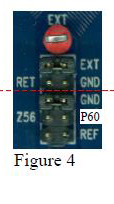 To measure the impedance of the ground electrode relative to the external electrode, position the jumper (below the dotted line) as shown in Figure 4.
 To measure the impedance of the reference electrode relative to the external electrode, position the jumpers as shown in Figure 5. In these configurations, channel 56 of the nanoZ will be connected to the ground or reference electrode respectively, instead of Plexon electrode 60.
nanoZ to ADM6 Adaptor (for use with 128 channel headstages)

This is a (dual) nanoZ to ADM6 (aka CON/128) adaptor. It can be used to connect a 128 channel electrode array to two nanoZs (A & B) simultaneously. Each nanoZ measures the impedance of up to 64 electrodes relative to a return electrode (RET). By default the 128 electrode channels are connected to the two nanoZs as described in the tables below.
After an electrode array has been implanted, the impedance of the electrodes is typically measured relative to the ground electrode (GND) within the electrode array. Prior to implantation, the impedance of the electrodes, including the ground and reference electrodes, can be measured relative to an external electrode (EXT) that is not part of the array. This is particularly useful for verifying the integrity of the ground and reference electrodes prior to implantation.
 To measure impedance relative to the ground (GND) electrode within the array, position the jumper (above the line) as shown in Figure 1 to the left. This configuration is typically used for in vivo impedance measurements of chronically implanted electrode arrays.
 To measure the impedance of the electrodes relative to an external electrode (EXT), position the jumper (above the line) as shown in Figure 2. The external electrode should be connected to the red test point marked EXT on the adaptor and placed in the same beaker of saline as the electrode array.
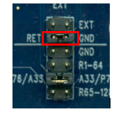
 Channel 33 of nanoZ A can be used to measure either electrode 76, the reference electrode for channels 1-64, the reference electrode for channels 65-128, or the ground electrode.
To measure electrode 76 (P76) position the jumper (below the line) as shown in Figure 3 to the left.
 To measure the ground electrode (GND), position the jumper as shown in Figure 4 to the left.
 To measure the reference electrode for channels 1-64 (R1-64), position the jumper as shown in Figure 5 to the left.
 To measure the reference electrode for channels 65-128 (R65-128), position the jumper as shown in Figure 6 to the left.
Note that if you are measuring impedance relative to the ground electrode (as shown in Figure 1), then using channel 33 of nanoZ A to also measure the ground electrode (as shown in Figure 4) will yield a near zero reading.