
NeuroLight Optoelectrode
A customizable electrode for simultaneous neural recording and precise local optogenetic stimulation in awake, behaving studies.
Precisely control the µLEDs using the new NeuroLight Stimulator.
These optoelectrodes have recording sites and precisely defined µLEDs (10 x 15 µm), allowing for simultaneous recording and local optogenetic stimulation. For chronic experiments, the electrode features an extremely durable, yet flexible cable allowing for light-weight stereotactic head fixtures.
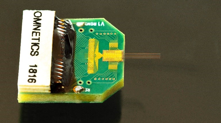
Acute
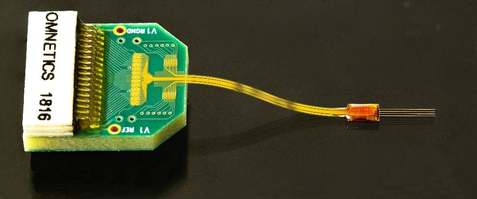
Chronic
NeuroLight probe assembly specifications allow for a maximum of one abnormal LED and two abnormal recording sites. Any NeuroLight probe which is suspected of not meeting these specifications prior to use in vivo may be replaced. A NeuroLight probe implanted or used in any other way cannot be returned or replaced.
NeuroLight Optoelectrode Specifications
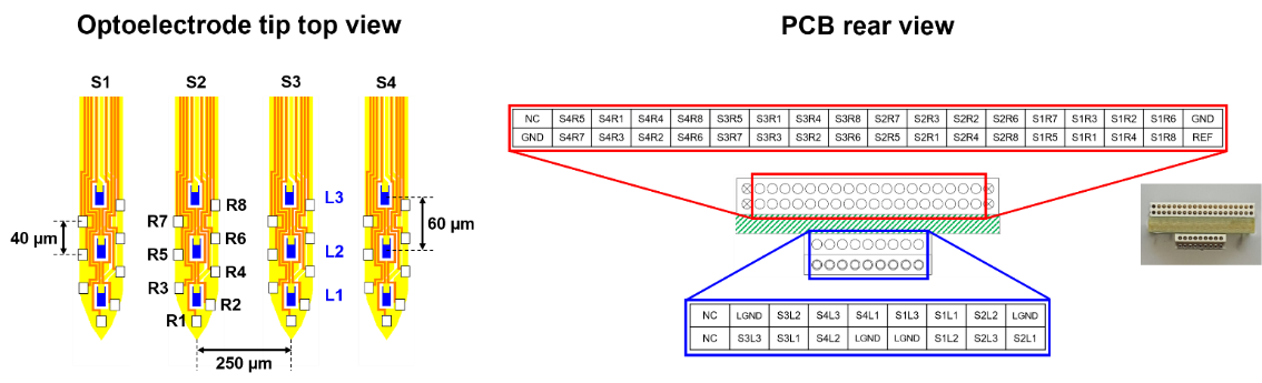
Technical Specs and Data Sheets
- NeuroLight Optoelectrode Data Sheet
- Specialty Probes, Electrodes and Arrays Data Sheet
- Electrode Comparison Chart
Videos
- “High-Density μLED Optoelectrodes for Local Circuit Mapping” – Webinar from July 8th, 2020
- “How to Use μLED Optoelectrodes: Surgery, Data Collection and μLED Control” – Webinar from July 15th, 2020
- Buzsaki/Yoon lab – Microdrive Assembly
- Buzsaki/Yoon lab – Probe Attachment to Microdrive
- Buzsaki/Yoon lab – uLED Probe Implantation
- Buzsaki/Yoon lab – Silicon Probe Recovery
- Buzsaki/Yoon lab – OSC1lite + Probe Setup
- Buzsaki/Yoon lab – Testing + Stimulation with OSC1lite
Design Citations
If you use one of these designs, please cite the following papers:
Mihály Vöröslakos, Peter C. Petersen, Balázs Vöröslakos, György Buzsáki
DOI: 10.1101/2020.12.20.423655
Mihály Vöröslakos, Hiroyuki Miyawaki, Sebastien Royer, Kamran Diba, Euisik Yoon, Peter C. Petersen and György Buzsáki
View the preprints and designs →
- Kim K, Vöröslakos M, Seymour JP, Wise KD, Buzsáki G, Yoon E. Artifact-free and high-temporal-resolution in vivo opto-electrophysiology with microLED optoelectrodes. Nature Communications. 2020 Apr 28;11(1):1-2.
- Navas-Olive A, Valero M, Jurado-Parras T, de Salas-Quiroga A, Averkin RG, Gambino G, Cid E, Liset M. Multimodal determinants of phase-locked dynamics across deep-superficial hippocampal sublayers during theta oscillations. Nature Communications. 2020 May 5;11(1):1-4.
ESD can permanently damage the micro-LEDs. Currently, there is no ESD protection circuitry integrated to the PCBs to protect the micro-LEDs on the optoelectrode. It is important that you discharge yourself before handling the micro-LED optoelectrode PCBs, especially when handling them in dry environment.
It is also recommended that you use ESD protection equipment (e.g. ESD-safe mats and wrist straps) and ESD-safe (dissipative) tools for handling if available.
Current drivers are generally a safer way to use your µLEDs but if you choose to use a voltage driver follow the I-V curve carefully and consider placing a high precision resistor in series and monitor current as well.
Any oscilloscope or voltmeter would work well across your resistor in this case and ensure you know the current. This is also a simple way to make your own I-V curve if you want to evaluate the µLEDs on your own.
Plexon recommends that the NeuroLight Stimulator be used to control the µLEDs.
A turn-on voltage between 2.8V and 7V is considered usable, although near 3V is typical.
If the I-V curve is flat, i.e. there is no current at any voltage, then the LED is open. Please do not use. If the turn-on is higher than 7V, it is also considered damaged.
If the I-V curve is linear (I=a*V) then there is a short and that too is faulty.
A normal working range is 1000 kΩ to 1.5 MΩ. Outside of that, you are not likely to see spiking activity.