
Are you thinking about adding optogenetics to your lab? There is no shortage of articles discussing light sources and fiber optics, however the sheer volume of information itself can be overwhelming, in particular since so many sources of information cover a wide range of applications, from telecommunications to two-photon imaging. To help navigate this copious amount of information, this article will distill down this information to only discuss features relevant to optogenetic experiments.
Light sources, LEDs vs Lasers for Optogenetic Experiments
The first step in choosing your equipment is choosing your light source, in which you have two main options; lasers and LEDs. Here we will discuss both, and the advantages and drawbacks of each, and how to decide which will work best for your experiments.
The Advantages of LEDs
- smaller size
- lower cost
- last longer and are harder to damage
- eye-safe (will not damage your vision if your eye is accidentally exposed to the light)
- wider range of wavelengths available
The Advantages of Lasers
For optogenetic experiements, lasers really only have one advantage; that they can output significantly more power. As a result, choosing between a laser and an LED in most cases ultimately comes down to how much power you need; if it is more than an LED can provide, then a laser is the obvious choice, otherwise an LED will serve better.
However, it should be noted that the amount of power needed is commonly overestimated. The majority of early optogenetic papers used lasers simply because high-output LEDs designed for optogenetic experiments were not yet available. Due to the limitation in wavelengths available for lasers, they had to use frequencies relatively far removed from the peak excitation for most proteins (and also due to the lack of available wavelengths, the response curves for most proteins were not well characterized). Consequently many publications are using non-ideal wavelengths at a much higher power than would be needed if the peak wavelength was used; for instance 630nm is frequently used for red-shifted opsins like Chrimson or ReaChR, even though the peak wavelength is around 590nm, or 532nm is often used for Arch-3 even though it has a peak at 566nm. Ideally you want to use as little power as possible to get a robust response, as close to the peak wavelength as possible, as excess power can cause confounding effects in neurons (heat tends to increase neural activity, which can be particularly confounding for inhibitory stimulus), or even kill tissue1. For this reason, LEDs are usually better suited for the majority of optogenetic experiments, more so than is generally realized.
Another notable difference
Although not necessarily an advantage or detriment (depending on your experiment), another notable difference between lasers and LEDs is that lasers produce highly collimated light (that is the photons are travelling in parallel to each other and in the same direction, see the illustration below), as opposed to LEDs which act like a more common light source, and produces uncollimated light. This results in two practical consequences; the first is that with collimated light you can use a lower NA patch cable to transmit the light over longer distances with less power loss (why this is will be explained in the next section), and second is that the light exiting the bare fiber or fiber stub will also be tightly focused. The first consequence is usually not significant for most experimental setups, since a patch cable of only a meter or less is needed for most experimental setups, However, the second has implications depending on how the fiber will be placed in relation to the target area, and the size of the target area. Essentially, if the fiber can be precisely placed directly above the targeted area, and if size of the target area is comparable to the width of the fiber, then a laser can be used to provide discrete and precisely aimed stimulation; however if a more diffuse distribution of light is desired then an LED is preferable. In the case that you need to use a laser because you need a higher power output, but also need greater light dispersion, Plexon offers Lambda fiber stubs that disperse the light along a conical tip instead of a simple circular window2.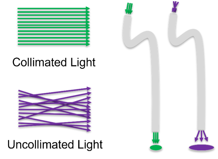
Summary – how to decide between an LED or a laser for optogenetic research
The first step is determining the optimal wavelength of light for the protein you are using. The Addgene plasmid repository has a useful glossary of commonly used proteins, including the peak response wavelength3. The next step is to determine the amount of power you need for activation (the Addgene website is again useful for this; searching for individual proteins will also provide a link for a list of papers citing that protein), and compare it to the maximum amount of power that the LED of that wavelength will provide. The PlexBright datasheet4 includes a useful table that provides the power output of the LEDs of all wavelengths offered, including the final light delivered after passing through a fiber (the amount of light provided in an acute experiment using a bare fiber termination) and fiber stub (used for a chronically implanted animal, bare fibers vs fiber stubs will be discussed below). Note that both the total power and power per square mm are listed; it is generally the power per area that you will want to refer to as that is more closely related to the power density per volume of brain that determines if sufficient light is being delivered to trigger a response.
Selecting an Optogenetic Patch Cable (also called a fiber or patch fiber)
Patch cable architecture
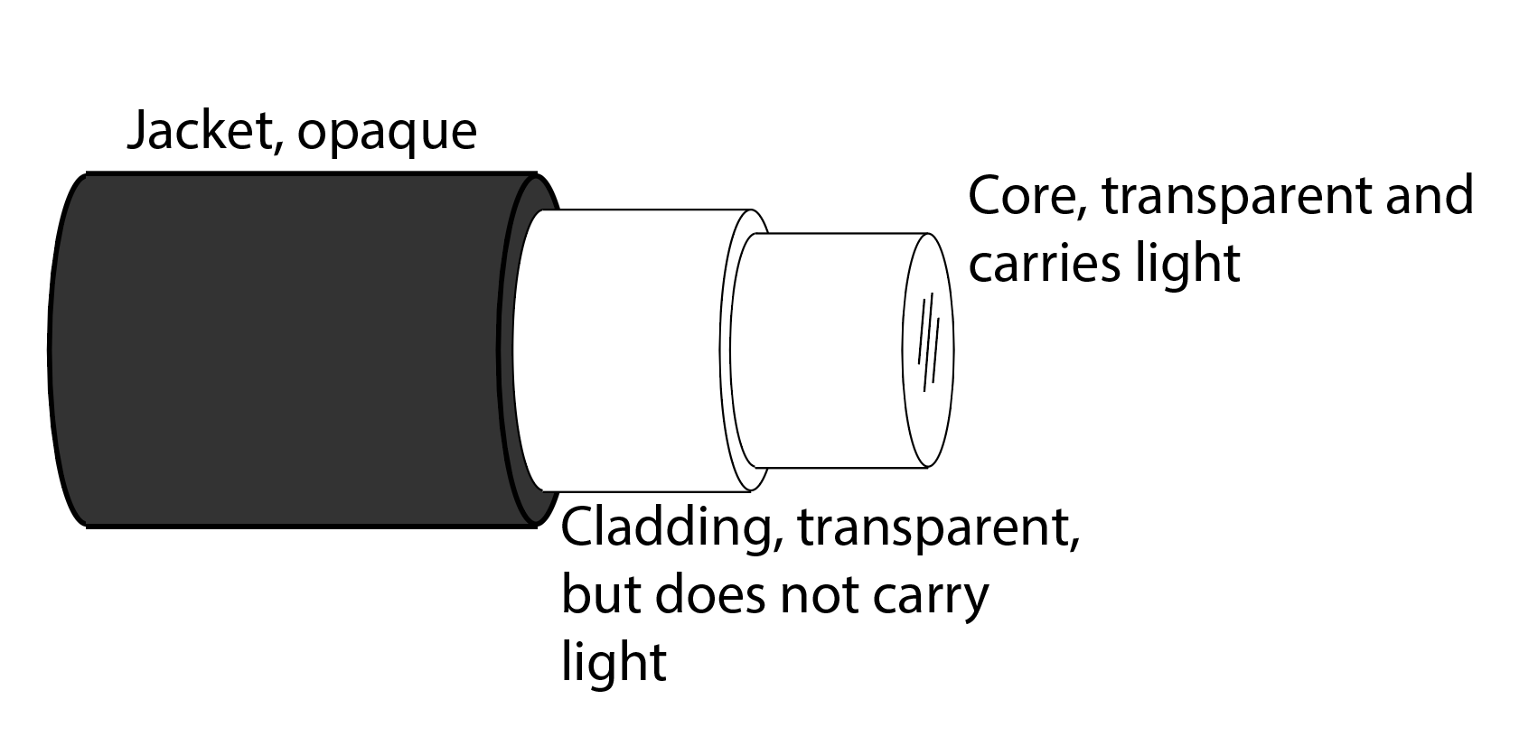
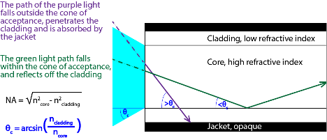
The simplest patch cable consists of just a transparent medium to carry the light; adding a jacket prevents internal light from escaping or external light from interfering with the signal. In this case any light that strays from the patch cable escapes or is absorbed by the jacketing, which will lead to significant power loss. Instead, the cable could be coated with a reflective coating, but even the most highly polished mirror only reflects around 99% of the light that strikes it; any type of light, flexible coating will be even less efficient, leading to significant power loss since any beam of light is likely to hit the sides of the fiber many times for any appreciable length. However, there is an optical phenomenon where light can be reflected with 100% efficiency when it is traveling in a material with a high refractive index and meets the junction of a material with a lower refractive index if it strikes the junction below a critical angle. This phenomenon is known as total internal reflection, and you may have witnessed it swimming under water; while looking straight up you can see the sky above you, but looking further out you can see the bottom of the pool/lake/ocean perfectly reflected at the surface of the water. Fiber manufacturers take advantage of this phenomenon by adding a layer of transparent material around the core with a lower reflective index than the core; this second layer is known as cladding, and is not intended to carry light, but reflect light back into the core. The critical angle that determines if a photon will be reflected or carry on into the cladding (and subsequently absorbed by the jacket) depends on the refractive index, n, of the two materials, where the critical angle θc = arcsin(ncladding/ncore).
What is NA, and how does it affect my stimulus light?
The Numerical Aperture, NA for short, is also calculated from the refractive index of the two materials, where NA =√(n2core – n2cladding). Since this number is related to the critical angle, you can think of the NA as the acceptance cone of the fiber, with an NA approaching zero only accepting light that is perfectly perpendicular to the termination of the core, and an NA approaching one accepting all light that comes into contact with the end of the core. If using a laser, a fiber with a high NA is not needed since the light is collimated, and essentially all of it will enter the fiber perpendicular to the fiber termination. By contrast with an LED, the higher the NA of the fiber, the greater the light that will be collected, and therefore more light transmitted through the fiber (see figure below).
Since the NA is determined by the difference in refractive indexes between the core and cladding, higher NA fibers need to dope the silica of the core to get a higher refractive index, and higher doping makes silica more brittle. Plexon offers two high-NA fibers; the high performance fiber (HP) with an NA of 0.66, and the high durability (HD) with an NA of 0.5. An HD fiber will collect and transmit less light from an LED compared to an HP, but it is much more flexible with a much smaller bending radius; it can be bent to a radius of just 2mm without creating a kink in the fiber, whereas the HP has a bending radius of 25mm (the bending radius refers to how tight of a circle a fiber can be looped into without damage). For this reason HD fibers are recommended for freely-behaving subjects.
Summary – selecting your NA
If using a laser for optogenetic stimulation, you do not need the light collecting features of a high-NA fiber since the light is collimated, so a low NA fiber is fine to use, and low NA fibers tend to be cheaper (low NA fibers also reduce power loss through Rayleigh scattering; however since that loss is not very significant for the fiber lengths used for optogenetic studies, we will not discuss it here). NA values of 0.22 or 0.3 are commonly used. For LED users, the higher the NA the better, however with behaving subjects the flexibility and durability of the fiber is an issue. We recommend a 0.66NA fiber for head-fixed or anesthetized subject for maximum light transmission, and a 0.5NA fiber for behaving subjects to provide enough flexibility while still maximizing light transmission.
Selecting the other specifications – length, core size, cladding size, terminations, and protective jacketing
When selecting the length, you want to provide sufficient length for experiment, but as little excess as is practical beyond that to minimize power loss. For head-fixed or anesthetized subject, you can simply move the light source as close to the subject’s area as possible without getting in the way and measuring the distance (adding a small percentage to that number to provide a comfortable about of slack to work with). For behaving animals, I would recommend using a piece of string to measure the longest distance from the commutator to the furthest reach in the animal’s behavioral area.
For the core size, you want to maximize the width of the core to be able to capture as much light as possible as determined by light window of your light source. All Plexon patch cables use a core of 200um since that is the optimal width for Plexon LEDs. If using a laser, check with the manufacturer for the optimal core width (values around 200um are common). Most fibers will also list the cladding diameter as well, however since the cladding is only used reflecting light and does not carry light, this value does not need to be selected; the manufacturer simply chooses a value to optimize the patch cable.
Plexon offers two different terminations for the light source end, FC and LC connector. FC are used for our table-top LEDs for acute or head-fixed subjects, while the lighter LC connector is the default connector used for our commutator-mountable compact LEDs. FC and LC connectors are also commonly used by other light source manufacturers, as well as a few others such as ST andd SMA connectors, which look similar to FC connectors and can easily be confused.
For the animal side termination, a bare fiber is the best choice for acute experiments since it reduces a light junction and therefore power loss. The bare fiber is inserted directly into the tissue to be stimulated. For chronic experiments, there needs to be a way to easily connect and disconnect the animal from the fiber; this is done by using a short length of just the core and cladding with a ferrule over one end for affixing to the subject’s skull as well as coupling to the patch cable. Plexon calls these fiber stubs, but they are also commonly referred to as canula. Plexon offers both 2.5mm diameter FC ferrules and 1.25mm diameter LC ferrules. They are designated FC and LC because these same ferrules are used within FC and LC connectors. The ferrules are just jacketing, and do not affect light transmission in any way. The FC ferrules are easier to handle, whereas the LC ferrules take up less space; in common practice researchers generally use FC ferrules with rats and LC ferrules in mice. The fiber stubs are coupled to the patch cable using ceramic sleeves; each Plexon patch cable kit comes with five ceramic sleeves included. Alternatively Plexon also offers magnetically coupled patch cables and fiber stubs, in which a magnet is affixed the to each ferrule, allowing easy connection without the need for a sleeve. The magnetic coupling also allows for the two ferrules to twist in relation to each other, acting as a commutator for behaving subjects. More information on magnetic fiber stubs can be found on the Plexon website4.
A final consideration for researchers using freely behaving subjects is if they need to protect the patch fiber from the subject. Plexon offers two options for protective jacketing, a more flexible mono-coil, and a more protective, but stiffer armoured jacketing. Since rats are both more aggressive and more tolerant to a heavier, stiffer cable, jacketing is almost always recommended for rats. Mice are more likely to be encumbered by jacketing, however the monocoil jacket may be reasonable compromise for anxious or aggressive subjects (such as in aggression or addiction studies).
Selecting your optogenetic fiber stub – ferrule, core size, NA and length
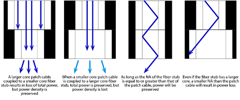
The fiber stubs ferrule should match the patch cable (which as mentioned is generally an FC for rats or similarly sized animals, or LC for mice and small birds). Generally the core size is selected to match the size of the target area (a larger core will spread light over a larger area), but neural insult is also a factor (a thinner core will cause less damage when inserted). Going from a larger core in the patch cable to a smaller core in the fiber stub will lead to a large loss of total power, however the power per mm2 will not be so significantly affected. In contrast a larger core fiber stub will collect all of the light exiting from a smaller core patch cable, but the power per mm2 will be reduced since that light will now exit from a larger window on the fiber stub. All of the fiber stubs sold by Plexon are approximately the same diameter or smaller as Plexon’s patch cables for this reason. For the majority of applications, if using a third-party fiber stub, it is not recommended to use a larger core.
As previously mentioned, the NA of the fiber can be though of as the “acceptance cone” of the fiber; similarly a larger NA patch fiber will disperse light out a wider angle at the other end. Coupling a patch cable to a fiber stub with the same or larger NA fiber stub allows all of the light emitted by the patch fiber to be collected by the fiber stub, whereas similar to going from a larger diameter core to a smaller diameter will lead to light loss, going from a large NA to small NA will also lead to a light loss. Although you may think that you could compensate for a smaller NA with a larger fiber stub core size, since you will still have light entering the fiber stub at an angle larger than the critical angle determined by the NA, it will pass through the cladding and be lost (see illustration below).
And finally, the length of the fiber stub will be mostly determined by the depth of your target area, however your surgical technique will also play a role. The more common approach is to drill a craniotomy large enough to pass the ferrule, and insert the implantable length fully into the brain, in which case the fiber stub length should match the target depth from the pial surface. Alternatively, to be as minimally invasive as possible, a hole just large enough to pass the fiber itself can be drilled, and the ferrule sits on top of the skull. In this case you will need to add the thickness of the skull at that area to your fiber stub length.
Summary of steps to choose your optogenetic equipment: light source, patch fiber, and fiber stub
- Determine if your optogenetic power requirements can be met by an LED, if not use a laser. Your light source will also determine the connector to use for your patch cable.
- Choose your patch cable NA; if using a Plexon LED and patch cable, this will be a 0.66 HP cable for anesthetized or head-fixed subjects, and a 0.50 HD cable for behaving.
- Choose your ferrule size (FC for rats or larger animals, LC for mice or smaller)
- Based on your stimulation target, choose your fiber stub core size and implantation length. Also make sure to choose a fiber stub with the same or larger NA as your patch cable
- If you have any additional questions, contact a Plexon representative!
Plexon makes it easy to get started. Create a starter kit for your optogenetic experiment using our starter kit. Answer a few questions and our sales team will contact you to provide more information on the optogenetic equipment that will be best suited for your experimental design.
References
- Peixoto, H.M., Cruz, R.M.S., Moulin, T.C. and Leão, R.N. (2020). Modeling the Effect of Temperature on Membrane Response of Light Stimulation in Optogenetically-Targeted Neurons. Frontiers in Computational Neuroscience, 14.
- https://plexon.com/products/lambda-fibers/
- https://www.addgene.org/guides/optogenetics/
- https://plexon.com/customer-driven-innovation-magnetic-fiber-stubs/

Written by Nafi Yasar