There are several advantages to using LEDs versus lasers for optogenetics. LEDs are safer, come in more wavelengths, and are much less expensive than lasers. However, this all comes with the tradeoff that LEDs are less powerful. That is, they produce fewer milliwatts (mWs) of light compared to lasers. Therefore, when using LEDs, it is necessary to optimize the light path to ensure that the required amount of power reaches the brain region of interest to activate the opsin.
Some LEDs may have no trouble delivering the required amount of power. However, not all LEDs or LED wavelengths are created equal. For example, yellow and orange LEDs, which are used for halorhodopsin and archaerhodopsin, have some of the lowest power outputs, which is intrinsic to these LED wavelengths. Therefore, when using LEDs, it is paramount to minimize power loss along the light path. Here, I will discuss the different ways to minimize power loss along the LED > Patch Cable > Fiber Stub light path.
For this post, I will be referring to an optogenetic setup using Plexon’s compact LEDs, patch cables, and fiber stubs (Figure 1). In this setup, the compact LEDs magnetically attach to the bottom of a rotating commutator. The LEDs are connected to a patch cable that leads to implanted fiber stubs. This is a common setup for an in vivo experiment where the subject is awake, behaving, and freely moving. This is one setup, but there are many potential variations, which should be kept in mind as I discuss optimizing the light path. After reading this post, if you have a different optogenetic setup and would like to discuss optimizing your light path, please reach out to us at support@plexon.com.
Number of Junctions
A junction is wherever the light path is broken. In the setup we are discussing (Figure 1), the junctions occur where the patch cable connects to the LED and fiber stub. In the Plexon setup we are discussing, the junctions are minimized to two because the LEDs mount to the bottom of the commutator. When using an optical rotary joint, the light path is: LED > Rotary joint > patch cable > fiber stub, which introduces a third junction.
In a typical setup using a patch cable, junctions are unavoidable. However, efforts can be made to minimize the number, which is exceedingly important, as it is expected that 20-30% of power will be lost at each junction.
Light is lost because light transfer across the break is not perfect. One way to minimize loss across junctions is to consider your optical fiber specifications on both sides of the break.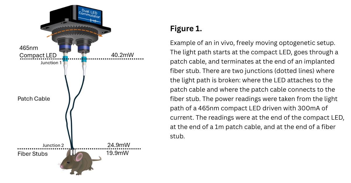
Matching Fibers Across Junctions
It is best to match specifications between the receiving and sending fibers to minimize the loss across junctions. The fiber’s diameter and the numerical aperture (NA) are the most important.
If you have a larger receiving fiber, while the majority of light down the path will continue, it will now be over a larger diameter, making the power per mm smaller (Figure 2A). And if the opposite is true, the receiving fiber is smaller in diameter, then the power per millimeter will be better maintained, but over a smaller area (Figure 2B). To split the difference, having the diameters match is the best compromise between maintaining power across the same area (Figure 2C). However, instability exists at the junction, and movement will occur, resulting in times when the fiber cores do not perfectly overlap. This is when the NA becomes important.

The NA is the angle of acceptance. In other words, the fiber core will accept light coming in from a certain range of angles. The larger the NA, the larger the angle range a fiber can accept light from. Having a larger NA will mean more light is captured across the junction (Figure 3). However, the tradeoff for a higher NA is that these fibers are more fragile and less resistant to bending. This is why Plexon offers two fiber options for patch cables: one with an NA of 0.66 (high-performance) and a second with an NA of 0.5 (high-durability). We usually recommend the high-durability fiber for experiments using awake, freely behaving animals. However, if you need high-performance fibers to maintain power levels, it is possible to get the fibers with monocoil or steel armoring. However, armoring reduces flexibility and increases weight, which is not ideal for all experiments and tends to be too heavy or too inflexible for smaller subjects.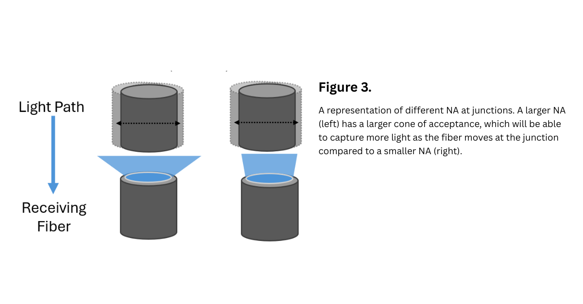
Use the patch cables and fiber stubs that are best suited for your experiment. However, matching fibers tends to be the best setup for maintaining power levels and minimizing loss across the junction.
Length of light Path
Unlike laser light, LED light is non-collimated. This means the light bounces around within the fiber optic and does not travel in a straight, orderly path. In practice, this is important because the bouncing light can escape from the fiber’s core. Therefore, the longer the light path, the less power will reach the region of interest. For in vivo setups with freely moving animals, another reason to minimize the length of the patch cable is that this will be less weight and pull on the animal’s head.
Additionally, since the light does not travel in a collimated path, at junctions, this means the light spreads over a larger area. As discussed above, this means fibers with larger NAs will capture more of the light across the junction.
Alternatives – Head-Mounted and HELIOs LEDs
If using the traditional patch cable and fiber stub cannot deliver the required power, even after optimizing the light path, then you can try alternatives that eliminate the need for a patch cable, which will reduce the number of junctions and minimize the light path length. For this purpose, Plexon offers head-mounted and wireless HELIOS LEDs.
Head-mounted and HELIOS LEDs attach directly to an implanted fiber stub, thereby eliminating the need for a patch cable and reducing the junctions to one.
Head-mounted LEDs have a small wire that attaches to a commutator for power. HELIOS LEDs are battery-powered and controlled via an infrared beam. There are pros and cons to both of these alternate LED types. Because HELIOS LEDs use batteries, they are heavier and have a limited run time. Head-mounted LEDs are powered, meaning they can be run indefinitely and are lighter, but the need for a power tether can be a limiting factor in setups where mobility is key. However, they both offer substantial power delivery since the LED is directly connected to the fiber stub.
In summary, minimizing junctions, matching patch cable specifications, and minimizing the light path are effective ways to optimize the light path in your optogenetic experiment and maximize the power delivered to your region of interest. If you need additional power, then head-mounted or HELIOS LEDs may be great alternatives. If you would like to discuss your experimental setup and ideas for optimizing your light path, we are happy to chat- just send an email to support@plexon.com.

Written by Kristin Dartt